Three Bugs in a SID Chip, and What the Die Photographs Told Me
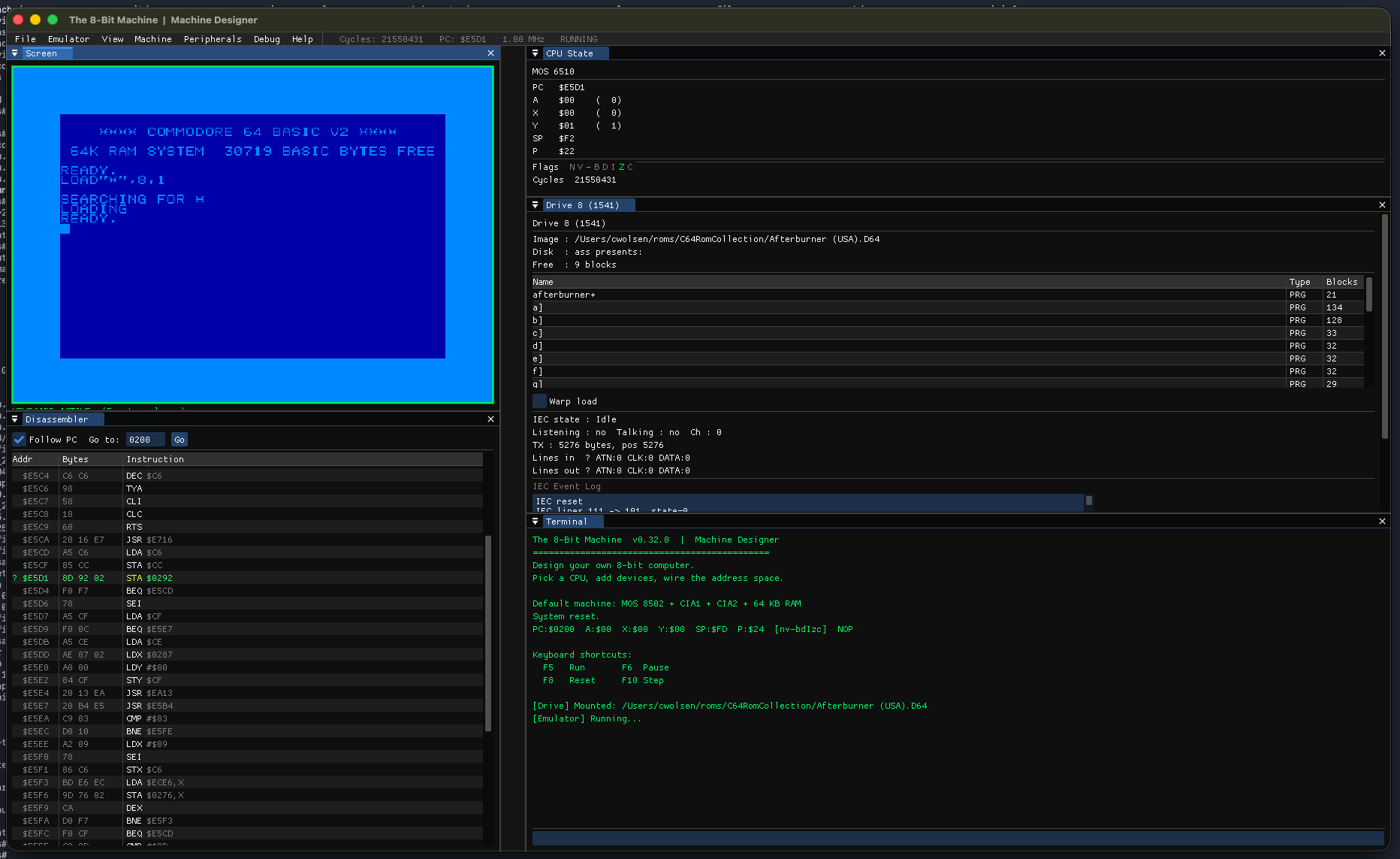
The 8-Bit Machine has had SID audio for a while. Three waveforms plus noise, ADSR envelopes, a filter, hard sync, ring modulation — all the pieces were there, and it made recognisably SID-ish noises. The problem with “recognisably SID-ish” is that it hides bugs. You only notice something is wrong when you compare it against the real thing.
v0.35.0 fixes three of them. What makes them interesting is that none were coding mistakes exactly. Each one was a place where I’d implemented a plausible model of the hardware instead of the actual one.
Hard sync wasn’t syncing
Hard sync is the effect where one oscillator forcibly restarts another. It’s the sound on countless C64 tunes — a harsh, metallic tearing that tracks the melody. Voice 3 wraps around, voice 1 gets slammed back to the start of its waveform mid-cycle, and the resulting discontinuity is full of overtones.
My implementation looked like this: detect when the source oscillator’s phase accumulator wraps, then set the target’s phase increment to zero for that sample.
That is not hard sync. That stalls the target oscillator for one sample and then lets it continue from wherever it happened to be. Real hard sync zeroes the target’s phase accumulator — it restarts the waveform. The difference matters enormously, because the entire character of the sound comes from that discontinuity. A one-sample stall produces a faint click. A reset to zero produces the tearing.
The fix is small. Compute a syncReset flag per voice from a snapshot of all three phases taken before any of them advance — so voice ordering can’t skew the result — then set the phase to zero rather than freezing the increment.
The part I’m happier about is how I verified it. Audio bugs are miserable to test, because “it sounds different” is not evidence — a stall also sounds different. But the SID exposes voice 3’s phase accumulator through a read-only register at $1B, OSC3, as the top 8 bits. So I could observe the accumulator directly.
Reading OSC3 over 20,000 samples with sync off gave 78 zero readings. That’s not noise, that’s exactly what you’d predict: OSC3 is phase >> 16, so it reads zero whenever the phase happens to land in the bottom 1/256 of its range, and 20000/256 ≈ 78. Turning sync on gave 108. The source oscillator wraps about 27 times in that window, and a true reset guarantees one exact zero per wrap. 78 + 27 ≈ 105, measured 108.
My first attempt at this test asserted that sync should produce ten times more zeros than no-sync, which failed — because I hadn’t thought about the baseline at all. The test was wrong, not the code. That’s worth saying out loud: a failing assertion is a hypothesis about the system, and sometimes the hypothesis is the broken part.
The filter had the wrong chip’s curve
The SID’s filter cutoff is set by an 11-bit register. My code mapped it to frequency with a straight line from 30 Hz to 12 kHz.
There are two problems with that. The first is that it’s linear, and the 6581’s cutoff response is anything but. The second, and worse, is the range: the 6581 doesn’t reach 12 kHz. It tops out somewhere around 7.5 kHz, and its floor is about 220 Hz, not 30.
So every filtered patch was coming out far brighter than real hardware, across the entire register range. Tunes that should sound warm and muffled sounded thin.
What I’d actually implemented was an approximation of the 8580 — the later HMOS-II revision, whose filter genuinely is linear. The two chips are different enough that C64 musicians care deeply about which one a tune was written for. So rather than pick one, v0.35.0 models both and lets you choose.
For the 8580 the relationship is exact. reSID computes its filter coefficient as w0 = 82355 * (fc + 1) >> 11, where 82355 is 1.048576 × 2π × 12500 — which unpacks to a clean linear sweep from 0 to 12.5 kHz across the register.
The 6581 is harder, and this is where it gets genuinely interesting. reSID models that chip’s filter at the transistor level, from microscope photographs of the die published by Michael Huth in 2008 and re-vectorised by Tommi Lempinen. There’s a per-register DAC table feeding a voltage-controlled-resistor model. It is a remarkable piece of reverse engineering and it is far more machinery than this project needs.
So I took the shape rather than the mechanism: a piecewise-linear curve through breakpoints that reproduces the measured response — nearly flat through the bottom third of the register, a steep knee around $300–$500, then flattening as it saturates near 7.5 kHz. It’s an approximation of a published curve, not measurements from a specific chip, and the code says so. Real 6581s vary noticeably between individual units anyway, which is part of their character.
Resonance was a number I made up
The third bug is the one I’d most like to pretend didn’t happen. My resonance mapping was a linear ramp: damping from 2.0 down to 0.1 as the resonance nibble went 0 to 15. Those numbers came from nowhere. They produced a filter that got sharper as you turned resonance up, which is the right direction, so it survived.
The real relationship is documented in the reSID source, derived from the same die photographs — from the resonance “resistor” ladder, 1/Q ≈ ~res/8. That’s a ones’ complement: Q ranges from 0.533 at res=0 up to 8 at res=14.
And at res=15? The complement is zero, and Q is, in reSID’s words, “theoretically unlimited, which is quite unheard of in a filter circuit.” Real hardware does something wild there. A digital state-variable filter with zero damping does something less charming: it self-oscillates and runs away until it slams into the output clamp. So res=15 is floored at the res=14 value — a deliberate divergence from the hardware, documented in the code, because the alternative is a horrible noise.
Amusingly, my pre-fix guess of “Q tops out around 2.7” — which I’d have defended if asked — was wrong in the opposite direction from the code. The old ramp reached Q≈10, closer to correct than my intuition was.
What I take from this
Every one of these bugs passed the “does it sound plausible” test for a long time. Each was found by going back to how someone else had reverse-engineered the actual silicon, and noticing that my model and their measurements disagreed.
The 6581 came out in 1982. People are still reading its die photographs to work out what it did. That’s the part of retro computing I find hard to let go of — these chips were designed under absurd constraints by small teams on impossible deadlines, and they’re still interesting enough four decades later that we’re arguing about the exact shape of a filter curve.
v0.35.0 also ships an expanded SID demo ROM with a resonance sweep and an LP/BP/HP mode cycle, because the bandpass and highpass paths had no test coverage at all. Which is its own small lesson.
The project lives at github.com/cwolsen7905/The8BitMachine, with builds for macOS, Linux, and Windows at www.the8bitmachine.com.